All interaction diagrams capture at least one interaction, which is the interplay of messages sent between objects over time for a specific purpose. Usually the most important interactions you document are the major use-case scenarios. In this context, we use the term scenario as an instance of a use case. Each use case has a generalized description of its most common scenario — its main course or main flow. In such a flow, you describe the interaction of participating objects as an ordered set of steps or actions that an actor (or system) takes as the flow plays out.
A participating object takes a set of actions, communicating the results of one or more of these actions in a message to another participating object — which (in turn) takes its own set of actions and communicates. Sometimes the participating object needs help from other object, so it requests a service in a message to another participating object, which (in turn) takes its own set of actions and communicates. When you draw an interaction diagram, you emphasize the message sequences among the participating objects, as shown in Figure 1, and (usually) hide the internal actions.
>

Figure 1: A basic sequence diagram.
In the sample diagram in Figure 1, you can see the basic features of a sequence diagram. You diagram the participating objects as vertical lifelines. These lifelines consist of an icon indicating the type of participant (such as an object or an actor instance) at the top of a dashed line where you can indicate the messages sent and received by the participating object. Show the messages among the objects as directed arrows from sender to target object. In this diagram, the FirstObject informs the SecondObject that It's Your Turn, and later, the SecondObject informs the FirstObject that Now It's Your Turn. The convention is that time passes as you read down the page, though you can turn the diagrams so time runs from left to right. As is typical in these diagrams, the messages alternate.
Place the interaction in the contents area of a frame, and then place the diagram interaction's title in the odd-shaped heading area (a rectangle with a cut-off corner) in the upper-left corner. The heading contains a prefix that describes the type of interaction you've placed in the frame. The sample diagram shows the interaction as a sequence diagram, so the descriptive prefix can be sequence diagram (for which the typical abbreviation is sd).
The frame and heading, new in UML 2, are applicable to all UML diagrams. Because UML 2 must be backward-compatible with previous work, the frame and heading are optional, and for the most part, you don't need to use them. However, use them with interaction and behavioral modeling, as they form the basis for behavioral decomposition (as shown later in this chapter).
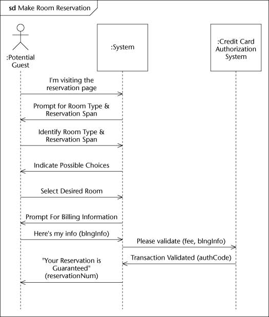
In Figure 2, you can see how the sequence diagram extracts and shows specific instances of communication among interacting entities. You don't show details of what must be done, just the messages — which makes it easy to see what's going on. This is an example of how UML uses abstraction to make your work understandable by hiding the details of internal behavior.
>

Figure 2: A sequence diagram.
>
dummies
Source:http://www.dummies.com/how-to/content/diagramming-an-interaction-scenario-in-uml-2.html
No comments:
Post a Comment